Digraphing
I haven’t made a post here in a while; I’ve been p busy at work.
So I guess I’ll write about it.
Without divulging too much about the application, let me try to explain the portion of software I’ve been designing/implementing for the past couple months…
The problem: customer wants a generic drag-and-drop interface for building custom chains of digital signal processing (and other processing) modules.
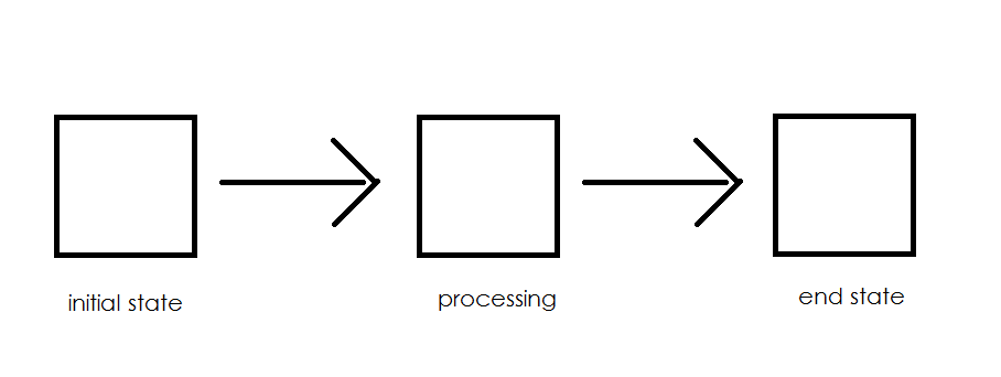
So, data comes in from a source module (say, data streaming from some hardware component), and then passes through a number of distinct processing modules (e.g. FFT, decimation, resampling, etc). The customer wanted the ability to visually arrange these modules to manipulate data in different ways.
I must admit that I know next to nothing about digital signal processing, but that’s alright; this piece of software is generic enough that it, too, is ignorant of the details of the actual processing.
The processing is in fact done on a separate computer running real time linux–the builder portion needs to “know” only enough information to control the processing flow and data flow.
For processing flow, the basic required information is: - a list of modules - a list of connections between modules
And for data flow, the program, for each module, should know: - initialization parameters - input parameters - outputs
A coworker was given the job of designing the UI–I was tasked with creating the underlying data structure that would keep track of all this. Some framework to represent the flow of processing from one module to another.
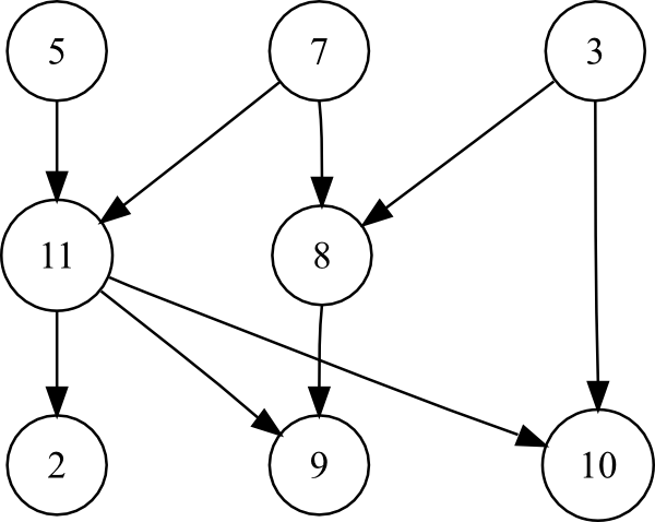
At first blush, a linked list seemed like the way to go. Modules would be nodes in the list, and each node would store a reference to the next node in the list. But we wanted it to be more flexible than that–modules could optionally branch to more than one subsequent module in the processing flow. A directed graph was more suited for this.
Modules would be represented as vertices in the graph, and edges in the graph described the processing flow. Like this:
vertices:
- source_module
- zeropad_module
- decimation_module
edges:
- source_module -> zeropad_module
- zeropad_module -> decimation_module
I found a simple, MIT licensed Directed Graph Library for .NET. I wanted to use this, but there were a couple drawbacks…
The first drawback was that the directed graph only stored vertices as strings. That is, I couldn’t specify a custom object as a vertex. The second drawback was that the library didn’t allow modules to be renamed after creating them.
So after adding a vertex called “v1”, a client of the directed graph library would need to reference that vertex always with the string “v1”–a bit limiting if I wanted clients of my class to be able to rename modules.
I solved this problem by generating and privately maintaining a GUID each time a new processing module was instantiated. This allowed clients of my “DirectedGraphManager” class to create human-readable module names that could be changed by the end user.
I used a dictionary to associate a GUID in the underlying directed graph with a Module object instance: digraphManager.lookupTable.
The DirectedGraphManager keeps track of this digraph behind the scenes, and client objects are able to change the module data easily without fear of corrupting the underlying digraph structure. So far this has been a pretty flexible design.

